Fusion 360 Weld Vertex points YouTube
Today are we talking about how to Notch / Cope Tube or Pipe in Fusion 360. Whether you are trying to build tube assemblies that you just need to model or you.
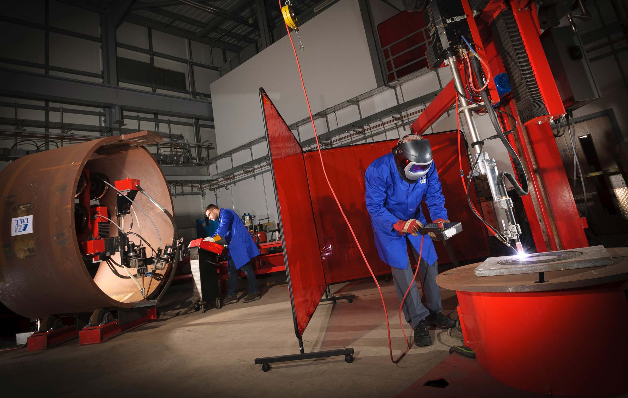
What is Fusion Welding? TWI
ArcFlat ® WELD TABLE ; Order ; Titan 25T™ CNC Press Brake; Order ; CNC PRODUCTS; Compare CNC Machines; FireControl;. Autodesk Fusion 360 is a powerful design CAD and CAM software that is free to use for hobbyists and startups with less than $100k revenue per year. This software can be downloaded from our website or directly from Autodesk.

Detailing of bolts and welds (AISC) IDEA StatiCa
We're back with another CAD tutorial! Today we are going in depth to learn the basics of using Joints in Fusion 360 to create assemblies. Joints are one of m.

Weld symbols in Fusion 360 drawings Page 4 Autodesk Community
Welding. Get Master Part Modeling with Autodesk Fusion 360 now with the O'Reilly learning platform. O'Reilly members experience books, live events, courses curated by job role, and more from O'Reilly and nearly 200 top publishers.
FUSION 360 Tips ASSEMBLIES, DRAWINGS AND WELDING YouTube
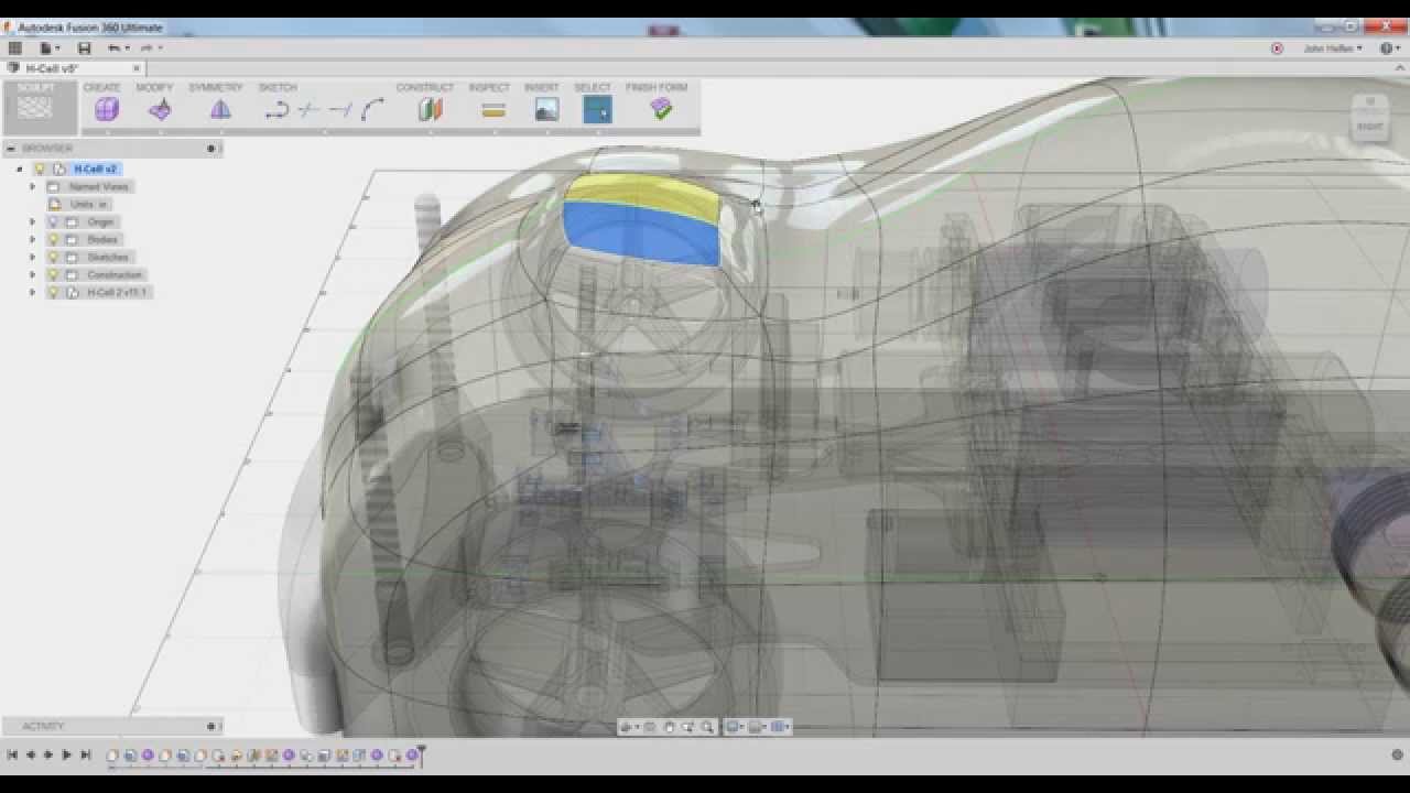
T-spline forms in Fusion 360 can be spilt by unwelding the edges of the t-spline. Then you can modify the form and re-weld vertices to create new forms and s.
Fusion 360 Pricing, Alternatives & More 2023 Capterra
reReddit: Top posts of September 2020. reReddit: Top posts of 2020. 51K subscribers in the Fusion360 community. Only posts directly related to Fusion are welcome, unless you're comparing features with other similar….
Fusion 360 Weld Symbols Fusion Blog
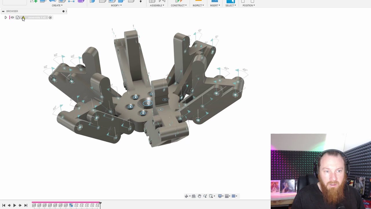
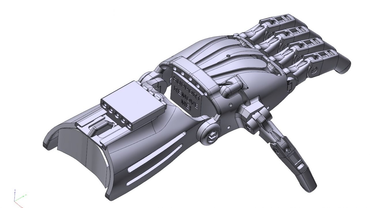
FUSION 360 Tips - ASSEMBLIES, DRAWINGS AND WELDING Make Tech 565 subscribers Subscribe 4.3K views 2 years ago ADELAIDE Look at these Fusion360 tips. Using this 6 finger robot gripper example,.
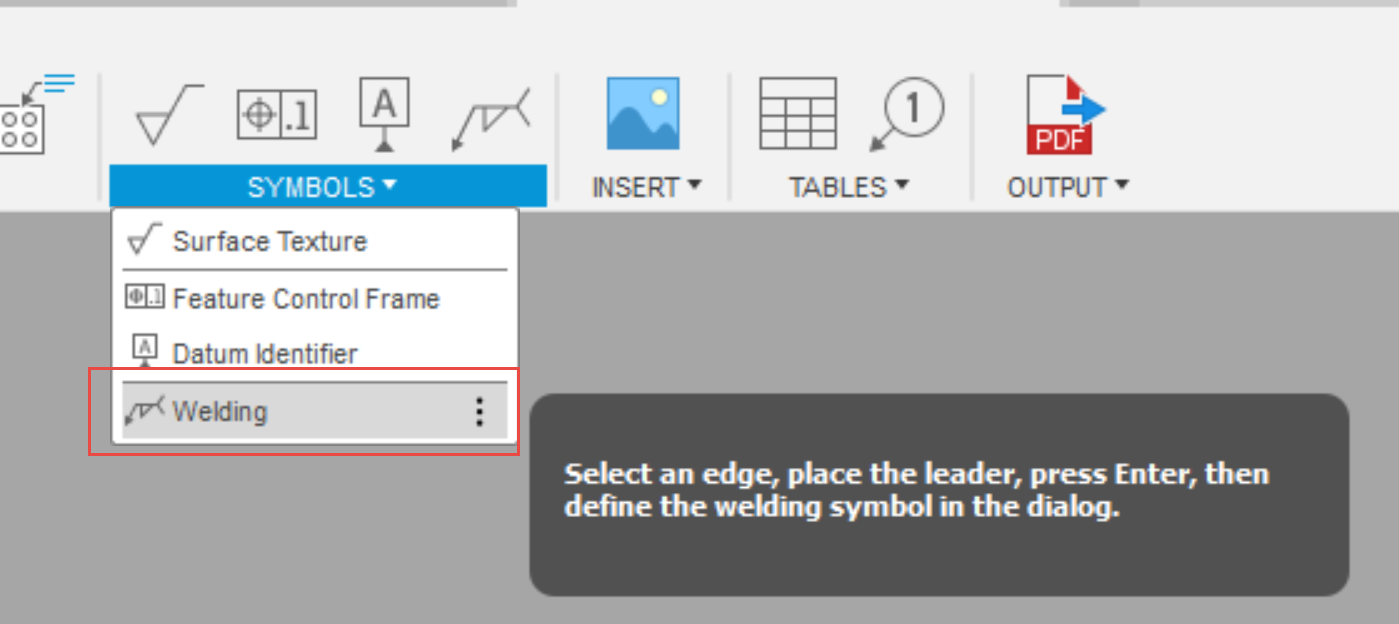
How to add weld symbols in Fusion 360 2D Drawing
This video is a comprehensive tutorial on how to create and use Joints in Fusion 360! Traditional modeling requires 3 constraints or mates to fully place and define a part inside an assembly,.
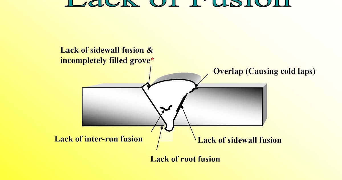
WQC Institute Of NDT What is meant by Lack of Fusion in welding?
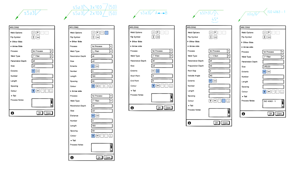
In the Welding dialog, you can view or change welding symbols properties for the current drawing in the Drawing workspace in Fusion 360. The table below shows the properties included for each standard revision, as well as their order within the Welding dialog. Parent page: Geometric tolerancing symbols Create a welding symbol

Fusion 360 Photoreal WeldsAutodesk Online Gallery
Oct 8, 2023 Products and versions covered Issue: How to add weld symbols in a Fusion 360 2D Drawing. Solution: In the symbols dropdown, select Welding to creating a welding symbol on your 2D Drawing. See Also: Fusion 360 December 2020 update Was this information helpful? Need help? Ask the Autodesk Assistant!

TIG Weld Like A Pro Hot Rod Network
My take on how to model Jimmy Diresta's steel shop table in Fusion 360. Check out Jimmy's YouTube channel:https://www.youtube.com/watch?v=5-oQncdBgasWant to.

How to use Weld Vertices command in Sculpt Environment Autodesk Fusion 360 YouTube
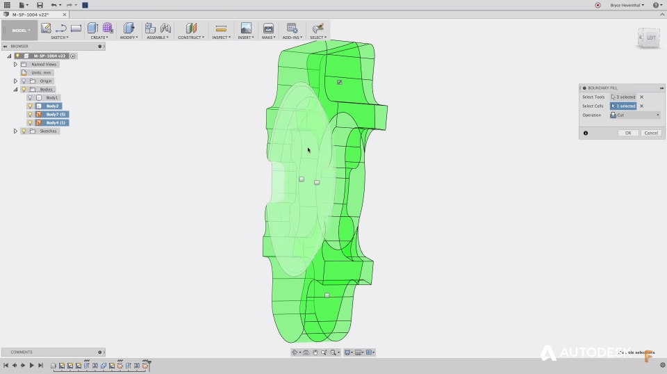
Solution: To join / combine bodies/components in Fusion 360 Click Design > Solid > Modify > Combine . From the Combine dialog, select the Target Body. Select Tool Bodies. In the Combine dialog, set the Operation to Join. The additional options are explained here: Join combines solid bodies into a single solid body.

Fusion & Welding Waterland Pty Ltd
Fusion 360 calculates the location of the new edge as a fraction of the overall face size. For example, 0.5 or 50% places the edge in the middle of the existing face.. The Weld Vertices command offers three options for welding vertices: Vertex To Vertex. Moves one vertex to another. Vertex To Midpoint. Moves both vertices to their midpoint.
Solved Weld Symbols in Fusion 360 promised for years now but are they really coming? Page
Fusion 360 remembers the Surface Texture, Feature Control Frame, Welding, and Taper and Slope symbols' last used settings. Once you place the symbol with all the desired settings filled out, you can continue adding the symbol without having to fill out the same settings.

Fusion 360 Photoreal WeldsAutodesk Online Gallery
1 [deleted] OP • 2 yr. ago I have created a sheet metal design that is designed to be welded during manufacturing. What options do I have to fill the gaps in the bend areas so that I can do a better stress simulation? This is a separate copy of the sheet metal design so no problems making it into a component or anything like that if necessary.
Fusion 360 Free Download Is There a Free Version? All3DP
When you create the flange feature, select the checkbox for "override rules" and more options will appear. Enable "2 bend corner override" and you can select the shape from the dropdown menu and adjust certain parameters. Since this change applies only to the bend, it will not affect other bends. When creating or editing a sheet metal rule, you.
